Secondary path A — Overmolding
A second shot bonds to the first.
A soft or coloured material is molded directly onto the rigid substrate, so grip, seal or finish is part of the part — not a separate piece added later.
Injection molding · Erie, Pennsylvania
Custom injection molding, overmolding, insert molding, prototyping and assembly — run from one shop floor in Erie, Pennsylvania.
Fig. 01 — Cavity fill, gate at left
Flow stage one
Flow starts with resin. Wall thickness, gate location and shrink are read against your geometry, and prototypes are molded so they behave like the production part.
Resin selection
Material matched to the part's load, temperature and surface requirement.
Prototype tooling
A first tool proves the geometry and the gate position before production tooling is cut.
Gate and fill review
Gate position, fill pattern and weld lines read against the drawing before the first shot.
Design feedback
Wall sections, draft and radii returned with comments before release to tooling.
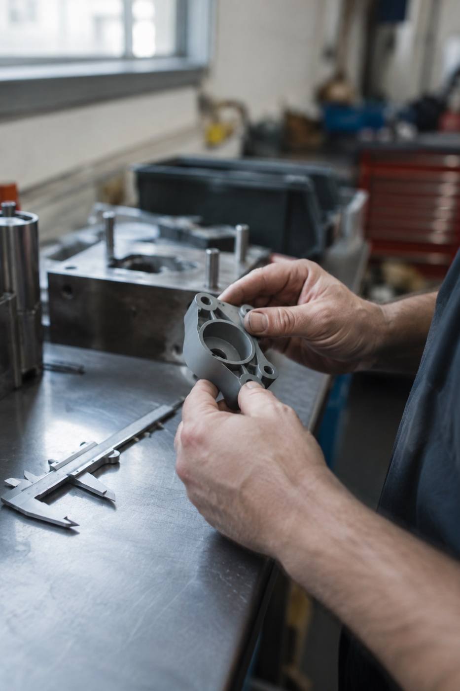
Stage 01 output — geometry, gate position and resin confirmed before tooling.
Flow stage two
Tools are built to your part, not to a catalogue. Cavities are laid out for balanced fill, then set and run on the press.
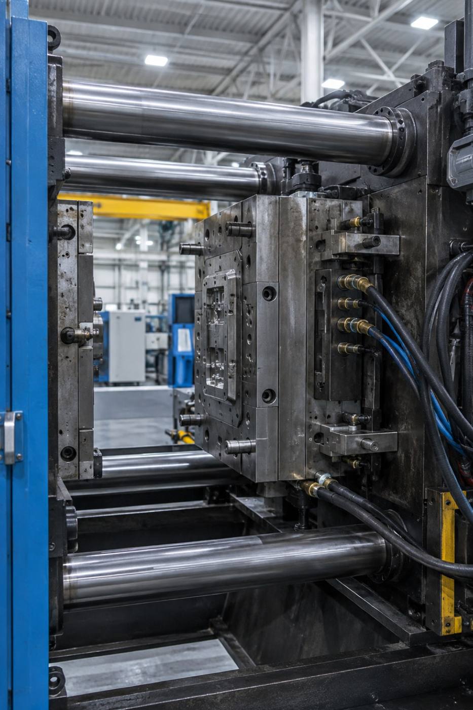
Cavity layout, gating and cooling designed around the part geometry.
From a single-cavity prototype tool through multi-cavity production tooling.
Shot size, hold pressure and cooling time established with the tool.
Flow stage three
Once the base part fills cleanly, a second shot or a placed component extends it. Overmolding and insert molding run as separate flow paths into the same tool.
Secondary path A — Overmolding
A soft or coloured material is molded directly onto the rigid substrate, so grip, seal or finish is part of the part — not a separate piece added later.
Secondary path B — Insert molding
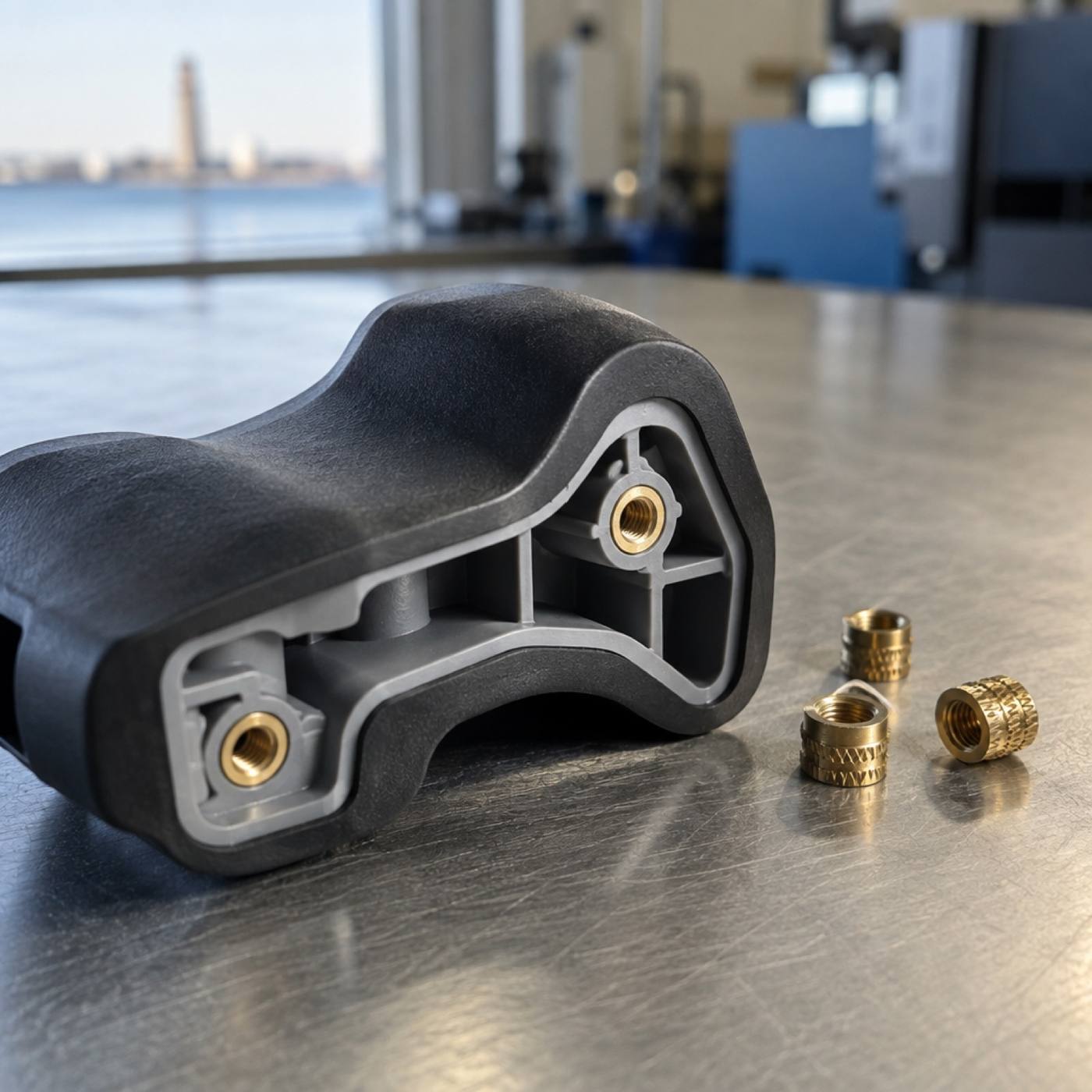
Threads, bushings and contacts are loaded into the cavity and molded in place. The insert becomes part of the molding instead of a later operation.
Where it fits
Overmolding and insert molding are decided at the design stage — substrate, second shot and tool layout have to agree before the cavity is cut.
Flow stage four
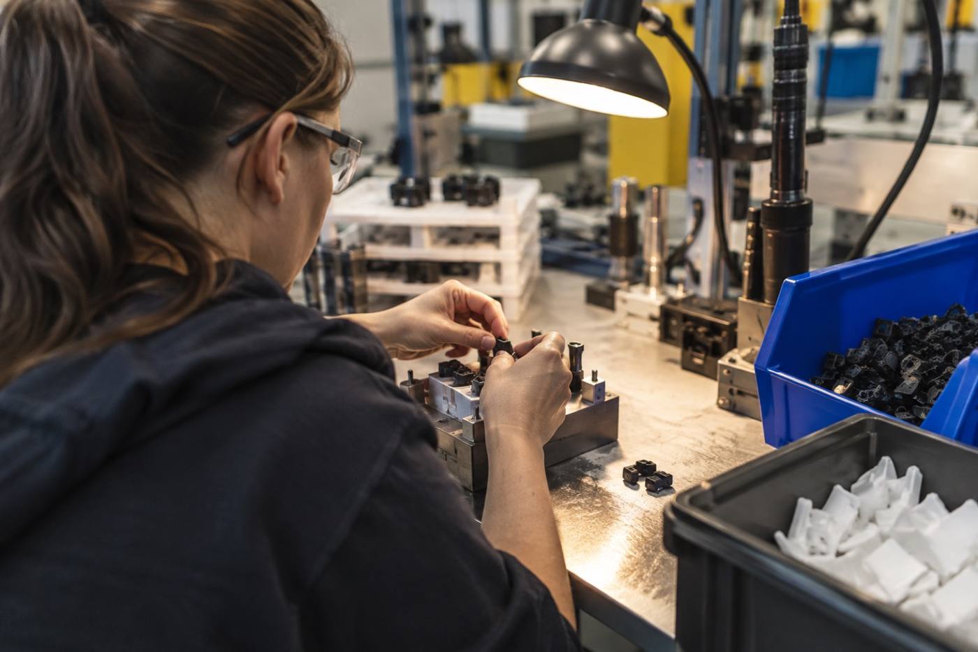
Molding finishes the part. Assembly finishes the job. Components, inserts and hardware are joined to the assembly drawing and checked before anything leaves the bench.
Parts come off the press and are checked against the drawing.
Threads, bushings and mating components are set into the molded parts.
Components are fitted and joined to the assembly drawing.
Finished assemblies are packed and staged for shipment.
Start the flow
Parts, tooling and assemblies are quoted from Erie, Pennsylvania. The more of the picture you send, the tighter the quote.