Boulder, Colorado — SLS · FDM · DMLS

Built layer
upon layer.

Additive manufacturing for engineers who think in cross-sections.

  • 01Rapid prototyping
  • 02Small-batch production
  • 03Powder bed and extrusion, in one shop
Section A–A In progress
Cross-section of an active build. Material rises from the plate upward until the geometry closes.

Layer 0 — Substrate

Every build begins as a cross-section.

LayerForge Additive is an additive manufacturing shop in Boulder, Colorado. We build parts by adding material one layer at a time — no molds, no tooling, no part-specific fixturing.

Send a model and we read it the way the machine does: as a stack of horizontal slices. Wall thickness, orientation, supports and the direction a load travels through the part all get settled before the first layer goes down.

That holds whether it is a single prototype or a small production run. The geometry you designed is the geometry that gets built.

Processes

SLS · FDM · DMLS

Scope

Rapid prototyping to small-batch production

Location

Boulder, Colorado
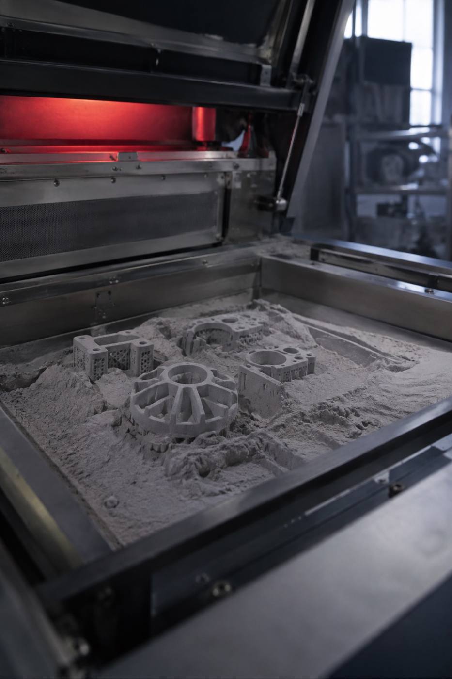
Open SLS build chamber with partially fused parts rising from a bed of grey polymer powder
Powder bed, mid-build. The surrounding material holds the part in place.

Layers 01–03 — Processes

Three ways to add material.

Pick a process by what the part has to do — carry a load, hold a tolerance, or take a shape that cannot be machined.

  1. 01

    SLS Selective Laser Sintering

    A laser traces each cross-section through a bed of polymer powder, fusing the slice to the one below it. The surrounding powder holds the part steady, so nested geometry, internal channels and unsupported overhangs come out of the chamber without extra fixturing.

    Polymer powder Functional prototypes Small-batch production
  2. 02

    FDM Fused Deposition Modeling

    Thermoplastic filament is laid down bead by bead along the toolpath. It is the most direct route from a CAD file to something you can hold, clamp and test — useful for jigs, fixtures, housings and form studies while the rest of the assembly is still being designed.

    Thermoplastic Jigs & fixtures Form studies
  3. 03

    DMLS Direct Metal Laser Sintering

    Metal powder is fused layer by layer into a dense part that behaves like metal, because it is metal. Best held back for the pieces that have to carry load, run hot, or fit into a space that machining cannot reach.

    Metal powder Load-bearing parts Production-intent
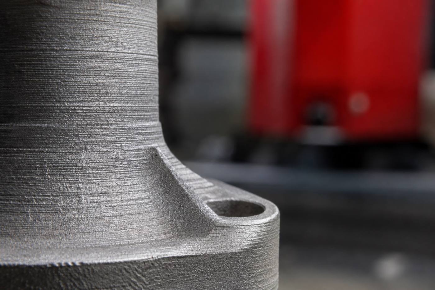
Macro view of a sintered metal surface showing fine horizontal layer lines
Layer height, read at the surface.

Layer detail

The layer line is a signature, not a flaw.

Every part carries the record of how it was made — a stack of horizontal striations at a fixed layer height. Surface finish, minimum feature size and the direction of those lines all follow from how the part is oriented inside the chamber.

Set the wrong way, they can weaken a part or spoil a mating face. We look at the model before the build and set the orientation so the layers work with the design instead of against it.

Working together

Send the model. We will tell you how it wants to be built.

Send the geometry — a STEP file, an STL, or a drawing with the critical dimensions — along with what the part has to do. We come back with a process, an orientation and a plan.

Most of the work happens before the machine starts: a wall that is too thin to hold a thread, an overhang that needs support, a fillet that saves an entire run.

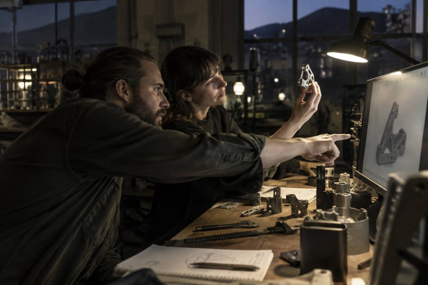
Two engineers examining a freshly printed part at a workshop bench under a task lamp
Reviewing a build before it goes back into the chamber.

Build sequence

From file to finished part.

Four steps, in order, every time — the same sequence the machine runs through, layer after layer.

  1. 01

    Review

    Send the model. We check wall thickness, tolerances and the features that will decide which process suits the part — before anything is quoted.

  2. 02

    Orientation & nesting

    The part is positioned in the chamber. This is where layer direction, support and the surface finish on critical faces are set.

  3. 03

    The build

    Material goes down layer by layer, from the build plate upward, until the geometry closes and the part is complete inside the bed.

  4. 04

    Post-processing

    Powder or supports come away, the part is cleaned up, and any finishing the drawing calls for is applied before it leaves the shop.

Build complete

Start a build.

Tell us what the part has to do and what it has to fit. We come back with a process, an orientation and a plan. Boulder, Colorado — SLS, FDM and DMLS.

What to send

  • 01

    The model. A STEP or STL file, or a drawing with the critical dimensions.

  • 02

    The quantity. One prototype, a handful, or a small batch.

  • 03

    The date. When the part has to be in hand.

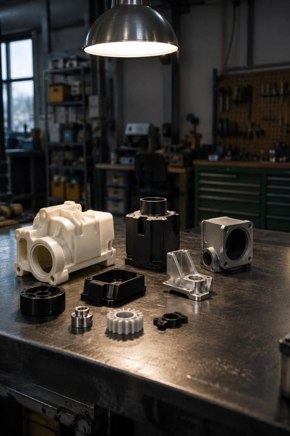
A batch of finished 3D printed parts arranged on a dark steel workbench
A small-batch run, out of the chamber and onto the bench.